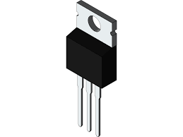
A thyristor is a 4-layer semiconductor device with P type and N type materials. An anode, a gate, and a cathode are the 3 electrodes of a thyristor.
The silicon-controlled rectifier is the most popular form of thyristor (SCR). No current flows when the cathode is negatively charged in relation to the anode unless the gate is pulsed. The SCR then starts to conduct and keeps conducting until the voltage between the cathode and anode is reversed or lowered below a specific threshold value. Large quantities of power may be switched or controlled using this sort of thyristor with a tiny triggering current or voltage.
Motor speed controllers, liquid-level regulators, pressure-control systems and light dimmers require thyristors.
What is a Thyristor?
Thyristors are a fascinating semiconductor device class. They have similar properties to other silicon-based solid-state components like diodes and transistors. As a result, it may be difficult to identify thyristors from diodes and transistors. To make matters more complicated, there are several distinct varieties of thyristors on the market.
In other cases, the only thing that distinguishes thyristors is a little feature.
A thyristor may also be recognized by a different name based on the manufacturer.
To use thyristors successfully in circuit design, you must first understand their particular qualities, limits, and relationship to the circuit. That’s why we’re taking the effort to sort it all out so you can figure out which thyristor is best for your application.
What are the Types of Thyristors?
There are three types of thyristors in general, as the following introduced detailed.
SCR – Silicon Controlled Rectifier
A four-layer solidstate current-controlling device known as a silicon controlled rectifier or semiconductor-controlled rectifier. General Electric’s commercial name for a type of thyristor is “silicon controlled rectifier.”
SCRs are primarily utilized in electrical devices that require high-voltage and high-power regulation. As a result, they may be used in processes requiring medium to high AC power, such as motor control.
When a gate pulse is applied to an SCR, it conducts like a diode. It is made up of four layers of semiconductors that create two different structures: NPNP and PNPN. SCR also includes three junctions, J1, J2, and J3, as well as three terminals, anode, cathode, and agate. It can regulate a large current and is commonly used in electrical circuits as a high frequency switch.
IGBT – Insulated Gate Controlled Bipolar Transistor
Insulated Gate Bipolar 2N2222 Transistor (IGBT) is a mix of Bipolar Junction Transistor (BJT) and Metal Oxide Field Effect Transistor (MOFET) (MOS-FET). It’s a kind of semiconductor that’s employed in switching applications.
The benefits of both transistors and MOSFETs are combined in the IGBT, which is a hybrid of MOSFET and Transistor. MOSFETs have a rapid switching speed and a high impedance, whereas BJTs have a high gain and a low saturation voltage, both of which are found in IGBT transistors. IGBTs are voltage-controlled semiconductors that allow for huge collector emitter currents while requiring practically no gate current driving.
Applications of IGBT
IGBTs are mostly employed in power applications. Standard power BJTs have a poor reaction time, but MOSFETs are better for quick switching applications. However, MOSFETs are more expensive when a greater current rating is needed. IGBTs can be used to replace power BJTs and MOSFETs.
In addition, as compared to BJTs, IGBTs have a lower ‘ON’ resistance, making them thermally efficient in high-power applications.
In the world of electronics, IGBT applications are many. IGBTs are employed in high power motor control, inverters, switched mode power supplies, and high frequency conversion regions due to their low on resistance, very high current rating, high switching speed, and zero gate drive.
GTO – Gate Turn OFF Thyristor
Turn off a Gate A thyristor, often known as a GTO, is a three-terminal bipolar semiconductor switching device with a current-controlled minority carrier. The terminals of a standard thyristor are anode, cathode, and gate, as shown in the diagram below. It has the power to switch off gates, as the name implies.
With a gate drive circuit, they can not only switch on the main current, but also turn it off. The GTO is triggered into conduction mode by a modest positive gate current, and it may likewise be shut off by a negative gate pulse. The gate in the diagram below has two arrows on it, which distinguishes the GTO from a regular thyristor. The bidirectional current flow via the gate terminal is shown by this.
Features of GTO
To switch off the GTO, a large amount of gate current is necessary. A GTO rated at 4000V and 3000A, for example, may require -750A gate current to turn off. As a result, GTO’s normal turn off gain is minimal, ranging from 4 to 5. GTOs are employed in low-power applications because of their huge negative current.
GTO, on the other hand, operates like a thyristor in the conduction state, with a tiny ON state voltage loss. The GTO switches quicker than the thyristor and can handle larger voltages and currents than power transistors.
GTOs come in a variety of shapes and sizes, with asymmetric and symmetric voltage capabilities. Symmetric GTOs are GTOs that have the same forward and reverse blocking capability (S-GTOs). Current source inverters employ them, however they are a little slower. Because of its decreased ON state voltage drop and stable temperature properties, asymmetric GTOs (A-GTOs) are commonly utilized.
The reverse voltage capabilities of these asymmetrical GTOs is significant (typically 20 to 25 V). These are employed in situations where a reverse conducting diode is connected across the circuit or when the reverse voltage across it would never arise. This article solely discusses asymmetric GTOs.
How Does a Thyristor Work?
When the P (cathode) and N (anode) are connected in series, three terminal pins result: anode, gate, and cathode.
When the anode and cathode, which are linked to the positive and negative terminals of a battery, are forward biased, the first and final PN junctions (j1 and j3) become forward biased owing to the depletion layer breaking. Because no current is supplied to the gate, the junction j2 remains reversed biased.
When current is applied to the gate, the j2 junction layer breaks, allowing current to flow across the circuit. The thyristor is triggered into a conducting condition when a sufficient positive signal current or pulse is delivered to the gate terminal.
A thyristor can either be fully on or off, unlike transistors, which can alternate between On and Off states.
As a result, a thyristor is ineffective as an analog amplifier yet effective as a switching device.
It has three modes of operation:
Mode of forward blocking
The junctions j1 and j3 are forward functioning, however j2 is reverse biased and does not allow current to pass.
Mode of forward conduction
The j2 depletion area is broken down when a positive voltage is supplied to the gate terminal. As a result, electricity begins to flow through the circuit, resulting in switch ON mode.
Blocking mode in reverse
We provide a negative voltage to the anode and a positive voltage to the cathode while keeping the gate open, causing j1 and j3 to be reverse biased and j2 to be forward biased. The passage of current is impossible because j1 and j2 are reverse biased.
Next Post: Fact About Semiconductors You Need To Know


